
Products
- Test smarter, not harder. Choose TestPlanner
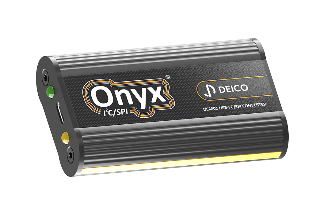
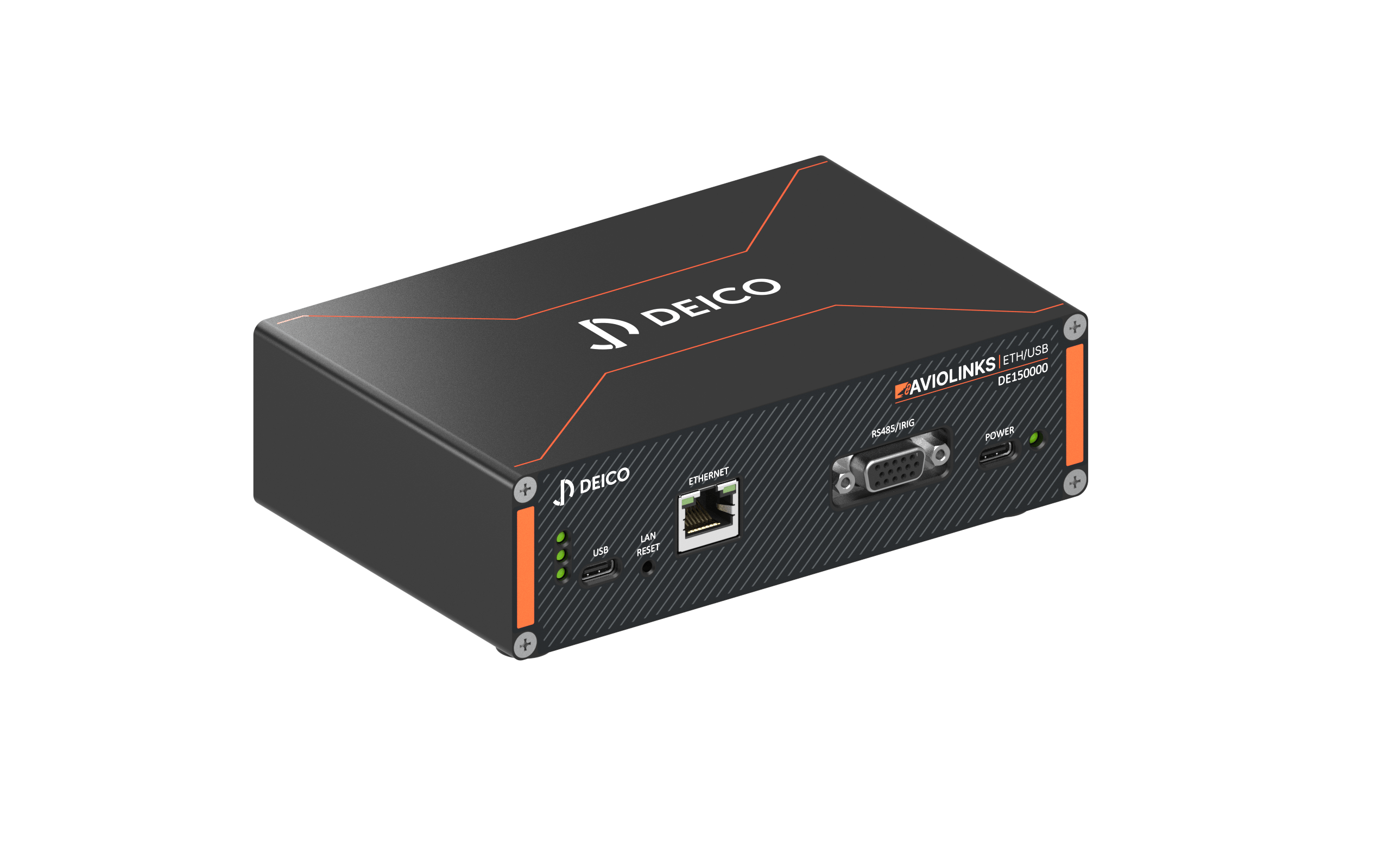
USB/Ethernet Converter Products
- DEICO offers a complete range for sub products to get the best performance.
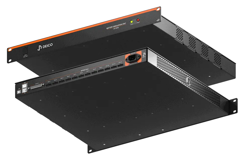
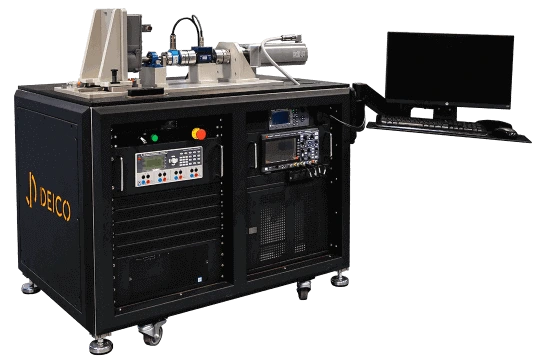
Battery Management System (BMS) Test Products
- Battery test products are safe, efficient, and accurate simulation products for new storage technologies.
- These products are equipped with advanced features.
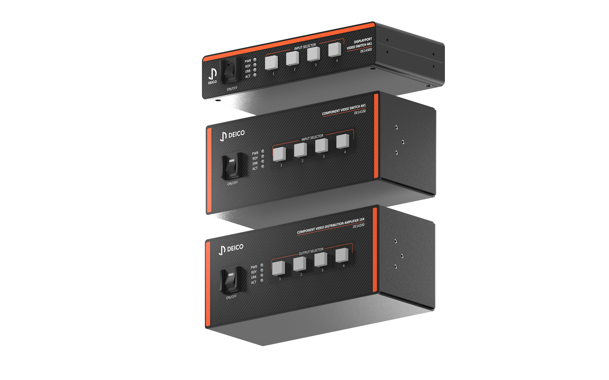
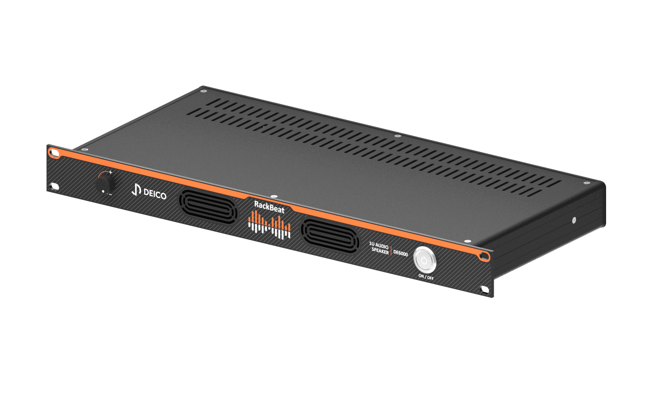
- Advanced video switching and distribution solutions.
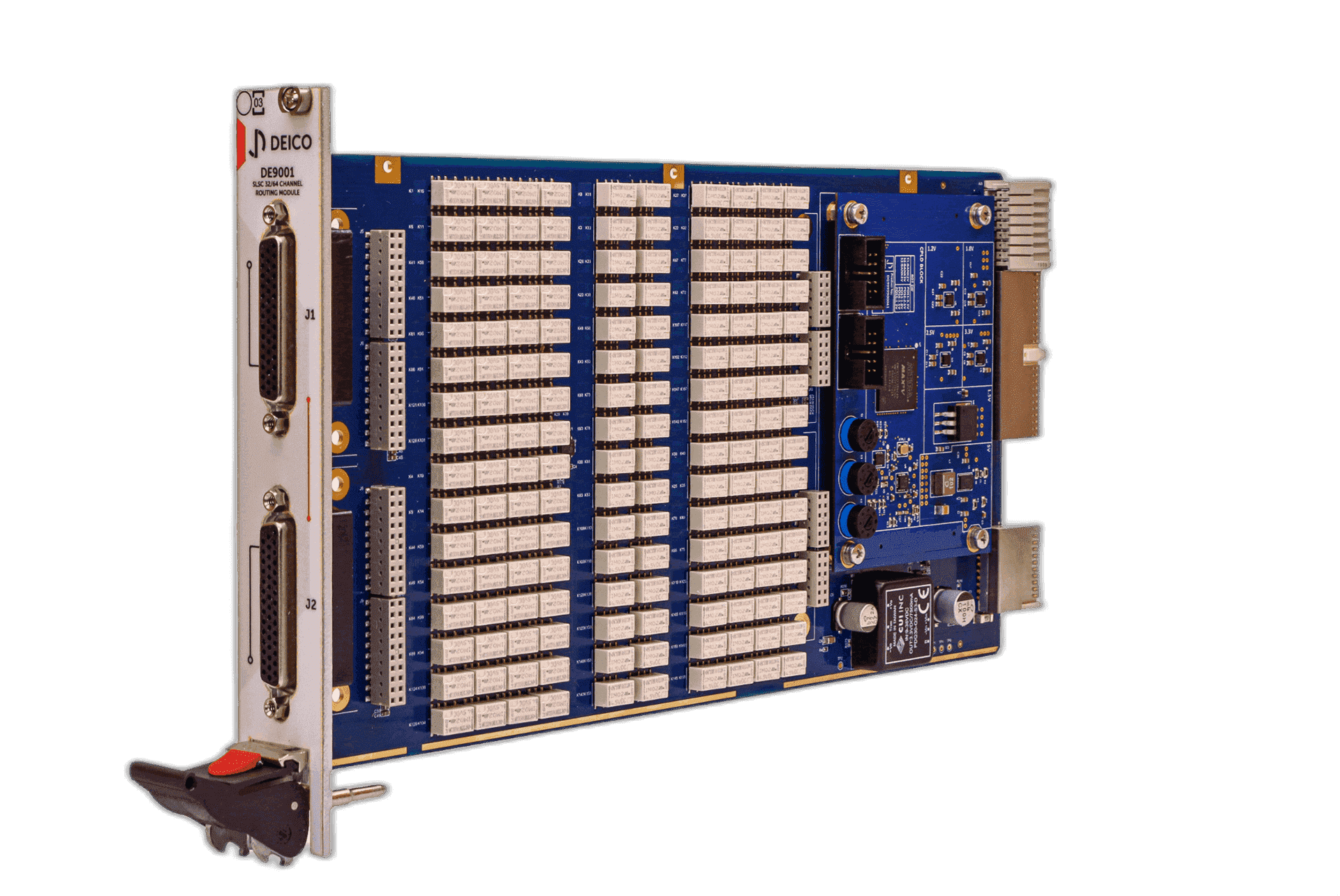
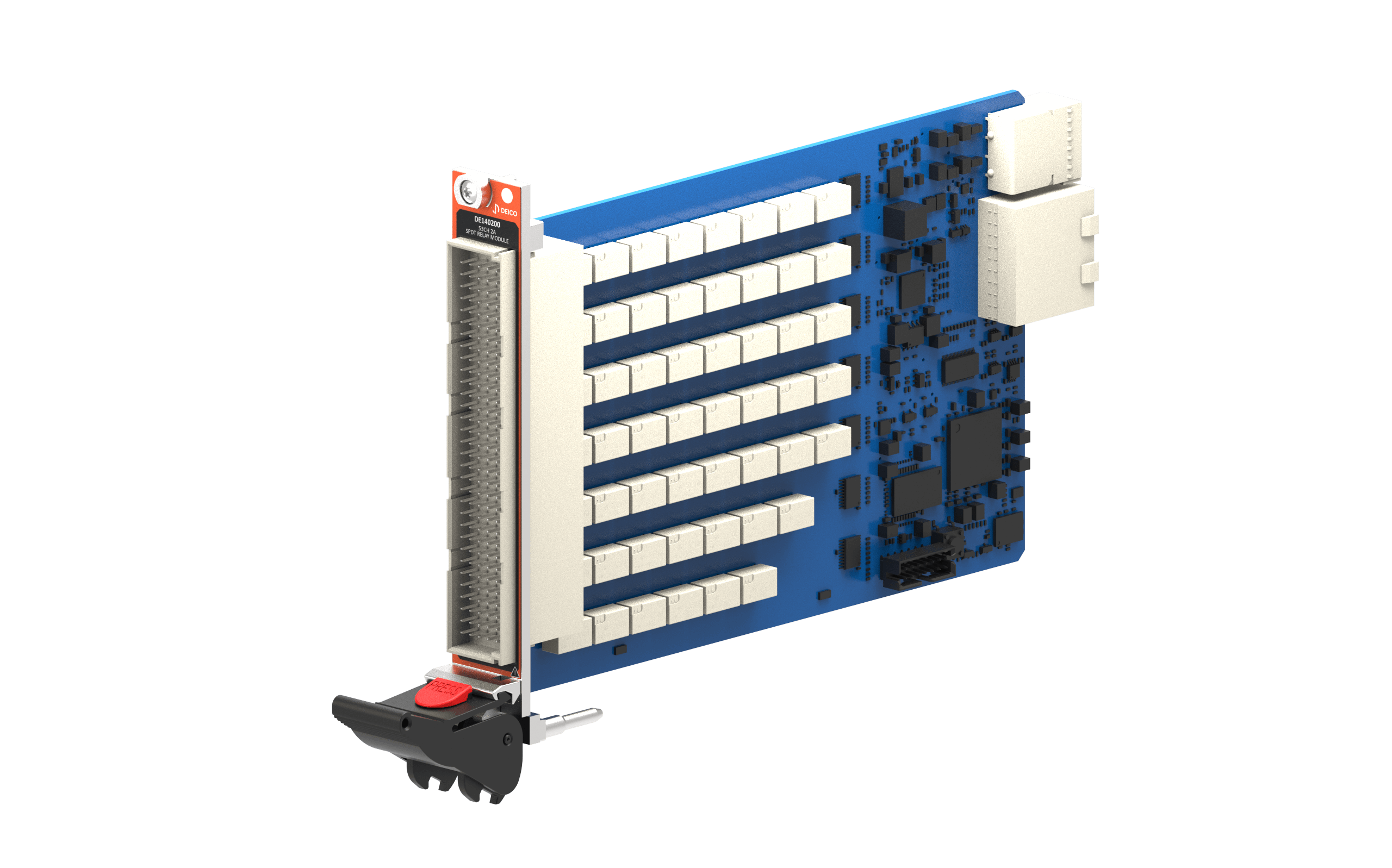
- DEICO ensures high testing capacity for advanced board designs.
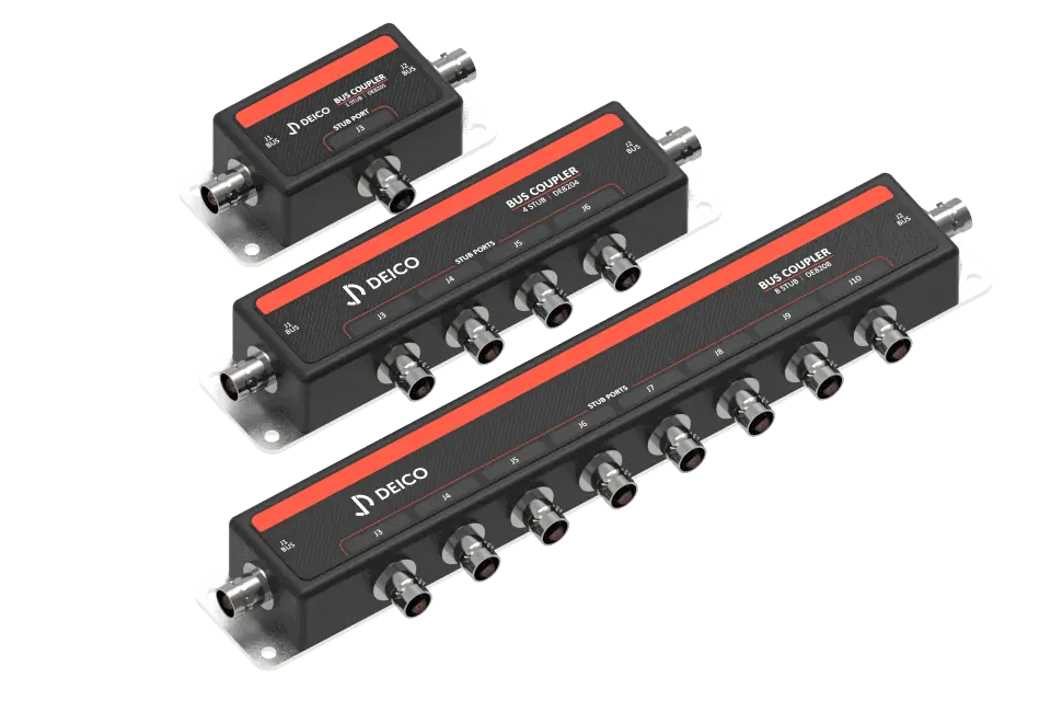
- DEICO offers diverse bus couplers to customer needs.
- SLSC reduces the time spent on common needs in test systems.
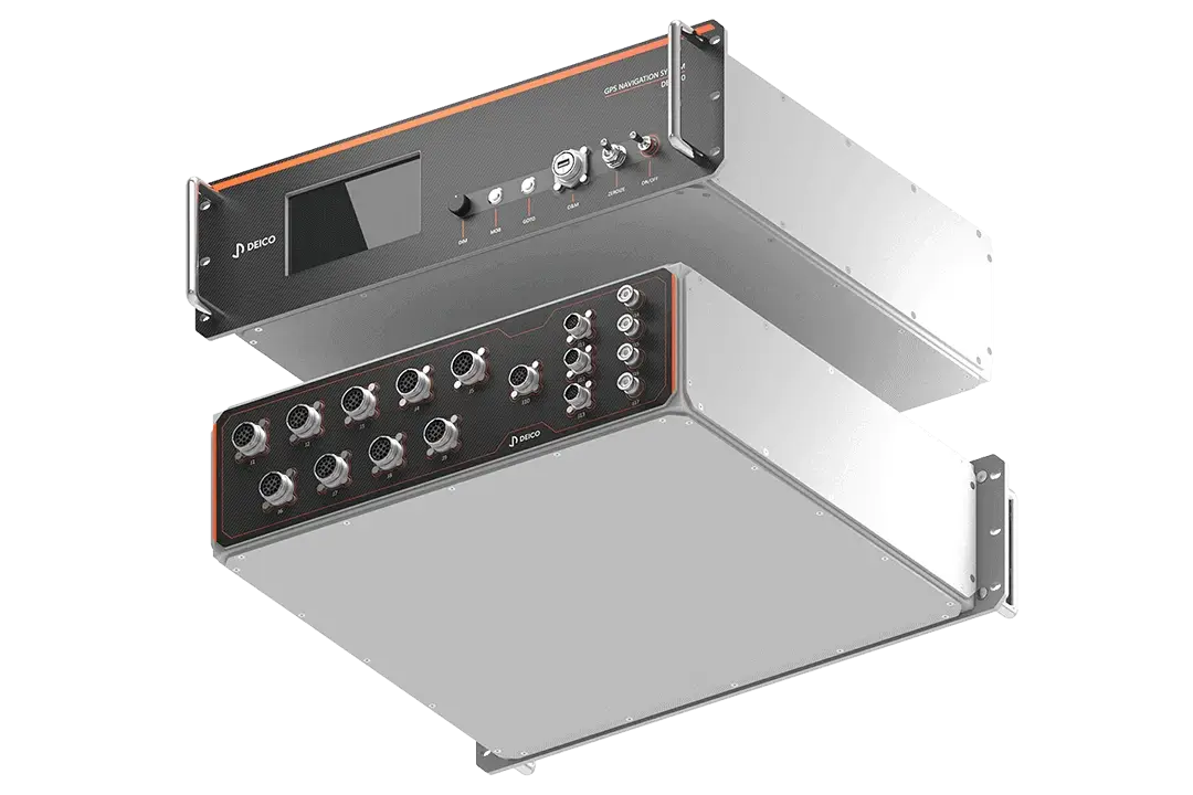
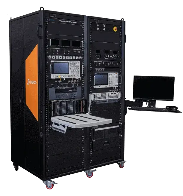
- These systems ensure reliability across diverse mission scenarios.
- DEICO's PXIe Systems offer comprehensive modular solutions for diverse industries.
Switching & Data Acquisition Systems
- All test systems need data acquisition structures to collect and analyze data.
- This series offers a wide range of test and measurement equipment products.
- JTAG Technologies is boundary-scan.
- DEICO avionics devices offer reliable, standard-compliant testing solutions.
TestPlanner
TestPlanner is a test automation software designed to help hardware test enginee..