Connect Your 1553 Bus
MIL-STD-1553 Data Bus Couplers
Wire any 1553 network in minutes. Pick your form factor, choose your stub count, and get flying. COTS couplers built for flight-ready platforms and benchtop test rigs alike.

DEICO MIL-STD-1553 Bus Couplers
One Standard. Three Form Factors. Any Bus Topology.
MIL-STD-1553 Bus Couplers Family
For Lab Setups & System Integration
Box Type Bus Couplers
The industry-standard form factor for benchtop and platform wiring. Available with 1 to 8 stubs and four termination options: non-terminated, left side, right side, or dual terminated.
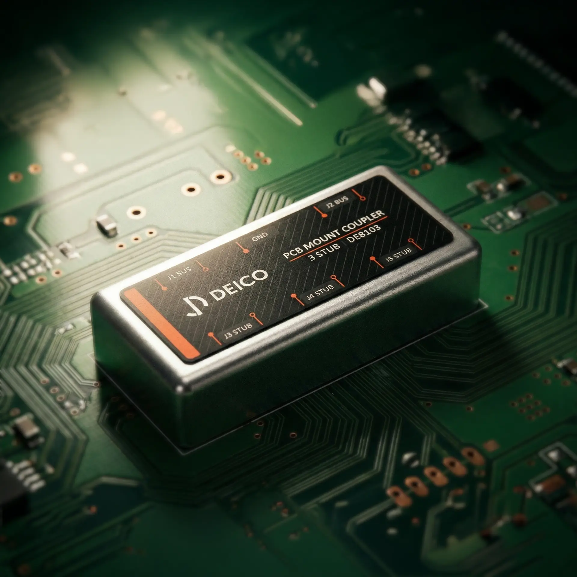
For Embedded & Board-Level Integration
PCB Bus Couplers
Same isolation and transformer performance as a box coupler, packaged for direct PCB mounting. Available with 3, 4 or 5 stubs and four termination options. Volume pricing starts at 10 units.
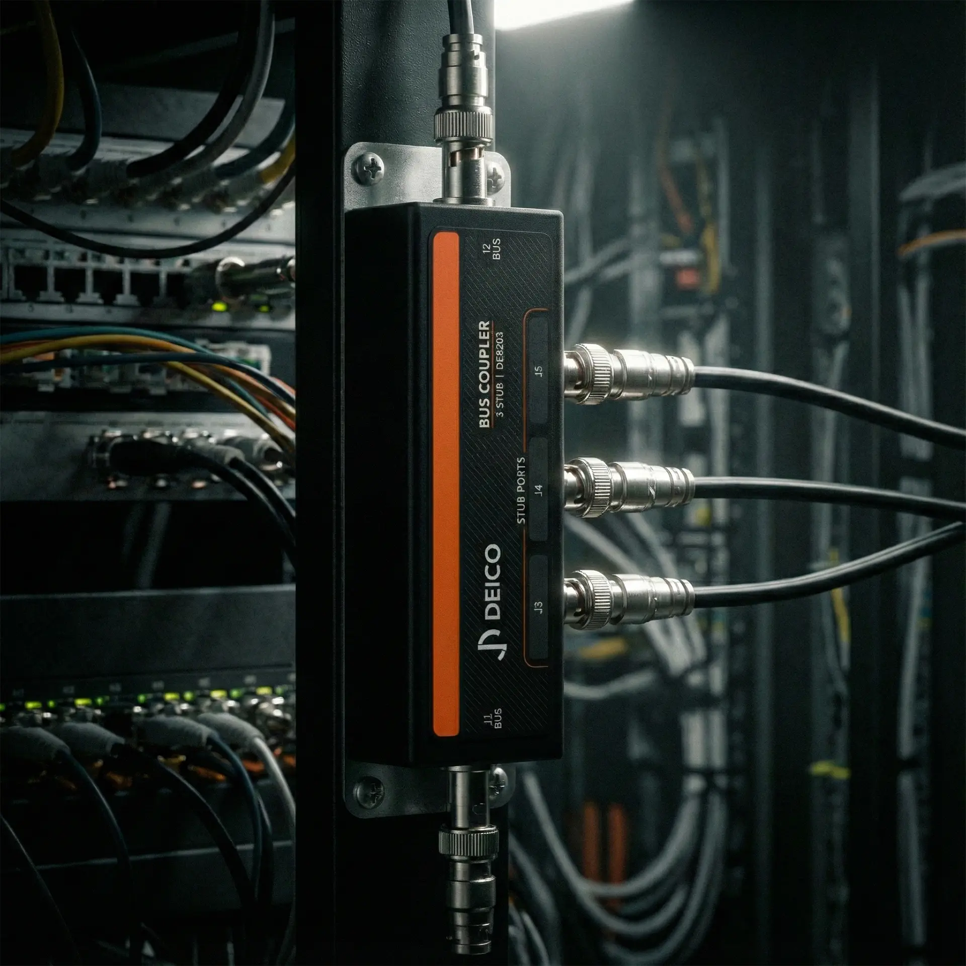
For Flight Hardware & Space Applications
Inline Bus Couplers
Compact inline form factor qualified for aeronautics and space environments. Available with 1 to 4 stubs, same-side or opposite-side stub configuration, and four termination options.
Your Spec, Our Build
Custom Bus Couplers
DEICO designs and manufactures fully customizable bus couplers tailored to specific customer requirements, offering flexibility in parameters such as stub count, form factor, switching, coupling ratios, resistor values, connector types, mounting, and environmental testing.
From quick lab hookups to flight-certified installations
The Right Coupler for Every Topology
Quick Lab Setup
Case:
3-RT Benchtop Test
Need a 1553 bus running on your desk by tomorrow? Grab a 4-stub box type coupler, plug in your terminals & bus controller, and start testing. No soldering, no custom cables.
Board-Level OEM
Case:
Embedded LRU Design
Designing a Line Replaceable Unit with onboard 1553? Drop a PCB coupler directly onto your board layout and keep the same isolation and transformer performance in a fraction of the space.
Flight & Space Certified
Case:
Aircraft / Satellite Bus Wiring
Platform integration with strict weight and space constraints? Inline couplers with aeronautics or space-grade qualification fit directly into the cable harness with no additional enclosure needed.
What is MIL-STD-1553?
MIL-STD-1553 is a military standard of a serial data communication bus that defines electrical, mechanical and other characteristics. MIL-STD-1553 systems typically use dual redundant physical layer featuring differential interface, time division multiplexing, half-duplex and 31 Remote Terminals, Bit Rate is 1 Mbit. Manchester code is used to present both clock and data on the same wire pair and to eliminate any DC component in the signal (which cannot pass the transformers)
MIL-STD-1553 was first published as a U.S. Air Force standard in 1973, and first was used on the F-16 Falcon fighter aircraft. It’s been used widely in aerospace and military applications since then.
The system consists of a Bus Controller (BC) controlling multiple Remote Terminals (RT) all connected together by a data bus. There may also be one or more Bus Monitors (BM); however, Bus Monitors are specifically not allowed to take part in data transfers, and are only used to capture or record data for analysis.
Single-Channel MIL-STD-1553 Bus Connection Example with Dual Redundancy (Two Identical Buses)

What is Data Bus Coupler?
Stubs for Remote Terminals, Bus Controllers or Bus Monitors are connected to the bus through coupling boxes that provide single or multiple stub connections. Bus coupler provides the necessary shielding, isolation resistors and transformer interface. For dual redundant systems, each bus needs its own bus coupler for a stub. An example connection scheme is given below, termination resistors can be either outside or inside of the coupler:
How Does a Bus Coupler Fit Into a MIL-STD-1553 Network?
A MIL-STD-1553 network consists of a Bus Controller managing up to 31 Remote Terminals over a dual redundant twisted-pair data bus running at 1 Mbit/s with Manchester II encoding. Each terminal connects to the main bus through a short cable called a stub. The bus coupler sits at the junction between the stub and the main bus, housing the isolation resistors and transformer required by the standard. Termination resistors (78.7 Ω) can be located inside or outside the coupler. In a typical setup, the main bus cable enters the coupler on one side and exits on the other, while one or more stub connectors branch off to individual terminals.
Sample Schematic of a Bus Coupler, 3 Stub Right Side Terminated
DEICO MIL-STD-1553 Bus Couplers use 59 ohm for Isolation Resistors (1 W, 1%) (R1-R6) and 78.7 ohm for Termination Resistors (2 W, %1) (R8).
Frequently Asked Questions
This is a common terminology difference in the avionics industry. A “Channel” typically refers to a complete, independent dual-redundant MIL-STD-1553 network (which includes both a primary and a backup path). A “Bus”, on the other hand, refers to one of those specific physical paths (usually designated as Bus A or Bus B). Because MIL-STD-1553 is inherently dual-redundant, a single “Channel” system will always require you to route and couple two separate physical buses (Bus A and Bus B).
Yes, both coupling methods can coexist on the same MIL-STD-1553 main bus. However, the physical layout must strictly adhere to the maximum length restrictions for each respective coupling method, and the main bus must be properly terminated at both ends. Transformer coupling is generally preferred in most avionics architectures due to its superior fault isolation and common-mode rejection.
The MIL-STD-1553B standard does not specify a strict maximum length for the main data bus. Instead, the limit is determined by acceptable signal distortion and cable attenuation. In practical applications, typical bus lengths can run up to 100 meters (328 feet).
Yes. The inline bus coupler product line includes variants qualified for space environments. Contact DEICO engineering to discuss specific environmental and qualification requirements for your mission.
MIL-STD-1553B specifies a maximum transformer-coupled stub length of 20 feet (approximately 6.1 meters). Direct-coupled stubs are limited to 1 foot, but direct coupling is not recommended for most applications.
The standard coupling transformer ratio is 1:1.41 (step-up from bus to stub). This ratio provides the required signal levels at the stub side while maintaining electrical isolation and a common mode rejection ratio greater than 45 dB at 1 MHz.
Yes. DEICO designs and manufactures custom bus couplers with configurable stub count, form factor, connector types, mounting options, transformer ratio, resistor values, and environmental test requirements. Contact sales@deico.com.tr with your specifications.
DEICO bus couplers use 59 Ω isolation resistors (1 W, 1%) on every stub. This equals approximately 75% of the standard 78 Ω bus impedance, as specified by MIL-STD-1553B.
All three form factors are available in four termination configurations: non-terminated, left side terminated, right side terminated, and dual terminated. Termination resistors are 78.7 Ω (2 W, 1%).
It depends on the form factor. Box type couplers support 1 to 8 stubs. PCB couplers support 3, 4 or 5 stubs. Inline couplers support 1 to 4 stubs. For stub counts beyond these standard configurations, DEICO offers custom designed bus couplers.
Box type couplers are standalone enclosures used in lab setups and system integration racks. They support 1 to 8 stubs and are the most common form factor. PCB couplers mount directly onto a printed circuit board inside an LRU or embedded system, available with 3 or 4 stubs. Inline couplers are compact units designed for aircraft and spacecraft cable harnesses where weight and space are limited, supporting 1 to 4 stubs with aeronautics or space-grade qualification options.
Check Pricing & Availability
Tell us your interface requirements. Our engineers will confirm compatibility and pricing in 48 hours.
+90 312 395 68 44
sales@deico.com.tr
We respect your privacy. No spam.